Bare crimp terminal "Y type / R type"
What is a crimp terminal?
Crimp terminals are essential components for connecting wires and electrical equipment and exchanging power and signals.
It was developed around 1925, before crimp terminals became popular and soldering was mainstream.
Advantages of using crimp terminals
In addition to using crimp terminals, there are other ways to connect wires and electrical equipment, such as soldering with insulation tape or direct wrapping.
But welding requires technical skills and can cause burns.
When secured with insulating tape, there is a risk of short circuits and it is difficult to assemble different wire thicknesses/types/standards beautifully.
Point crimp terminals eliminate the need to worry about burns or connections between different wires.
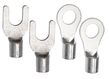
Bare crimp terminal
Two types: bare crimp terminal (round/R-type) and bare crimp terminal (open front/Y-type).
-
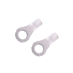
Bare crimp terminals (pill type/R type)
-
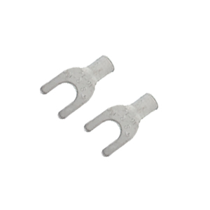
Bare crimp terminals (first open type/Y type)
In fact, there is no problem in choosing any crimp terminal.
Below we will introduce the advantages and disadvantages of bare crimp terminals and provide you with considerations when choosing them.
Terminal introduction
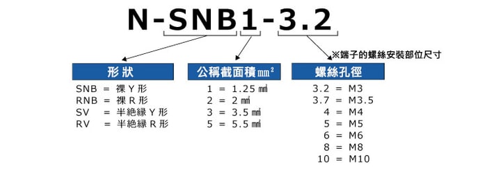
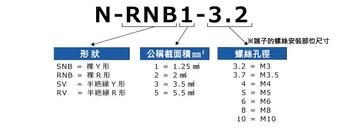
- 1. "Round type/R type" and "First opening type/Y type"
- The advantage of "round type/R type" is that it is safe.
- The advantage of "first opening type/Y type" is that it has good processability.
- Therefore, the focus of selection is to takesecuritystillProcessability。
| 〇Advantages | ×Disadvantages | |
|---|---|---|
| Pill type/R type | Good safety A bit cheaper than model Y For example, even if a screw is slightly loose, it will still hold *Looseness enough to lift the terminal may cause sparks. |
Poor operability Ex. The screws must be completely removed and installed |
| Pre-opening type/Y type | good processability Ex. Can be installed immediately without removing screws. |
Poor security Price is slightly higher compared to round shape If the screw is loose, it may fall off directly Ex. Risk of direct contact with electricity |
- 2. Advantages and Disadvantages of "Half Jueqi"
- The advantage of "exposed" is that it reduces working time and is cheaper than semi-insulated.
- However, if it is installed in an exposed place, there is a risk of direct contact with current, so heat shrink tubing must be used for insulation after installation.
| 〇Advantages | ×Disadvantages | |
|---|---|---|
| naked | Working hours can be shortened Cheaper than semi-insulated For example, place it where there is no direct contact, such as with a lid |
Poor security Depending on the installation location, insulation may be required later. |
The choice of crimp terminals is usually based on the user's preference.
Experienced engineers often make choices based on past experience.
However, if you have no experience, don’t know where to start when selecting a judgment standard, and have any questions or unclear points about crimped terminals, please feel free to contact us to answer your questions.
Feature
| Material | Oxygen-free copper |
|---|---|
| quantity | 100 |
Y type main dimension drawing
| model | Nominal cross-sectional area (㎜²) | Screw hole diameter | Dimensions of each part (㎜²) | Applicable wire standards | ||||||||
|---|---|---|---|---|---|---|---|---|---|---|---|---|
| ød2 | W | F | L | E | øD | ød1 | T | Stranded wire㎜² | AWG | |||
| N-SNB1-3.2 | 1.25 | M3 | 3.2 | 5.7 | 6.5 | 16.0 | 4.8 | 3.4 | 1.7 | 0.75 | 0.5-1.5 | 22-16 |
| N-SNBS1-3.7 | M3.5 | 3.7 | 5.7 | |||||||||
| N-SNBL1-3.7 | 3.7 | 6.4 | ||||||||||
| N-SNBS1-4 | M4 | 4.3 | 6.4 | |||||||||
| N-SNBM1-4 | 4.3 | 7.2 | ||||||||||
| N-SNBS1-3.7 | 4.3 | 8.1 | ||||||||||
| model | Nominal cross-sectional area (㎜²) | Screw hole diameter | Dimensions of each part (㎜²) | Applicable wire standards | ||||||||
|---|---|---|---|---|---|---|---|---|---|---|---|---|
| ød2 | W | F | L | E | øD | ød1 | T | Stranded wire㎜² | AWG | |||
| N-SNB2-3.2 | 2 | M3 | 3.2 | 5.7 | 6.5 | 16.0 | 4.8 | 4.1 | 2.3 | 0.80 | 1.5-2.5 | 16-14 |
| N-SNBS2-3.7 | M3.5 | 3.7 | 5.7 | |||||||||
| N-SNBL2-3.7 | 3.7 | 6.4 | ||||||||||
| N-SNBS2-4 | M4 | 4.3 | 6.4 | |||||||||
| N-SNBM2-4 | 4.3 | 6.4 | ||||||||||
| N-SNBL2-4 | 4.3 | 8.1 | ||||||||||
| N-SNBS2-5 | M5 | 5.3 | 8.1 | |||||||||
Type R main dimensions
| model | Nominal cross-sectional area (㎜²) | Screw hole diameter | Dimensions of each part (㎜²) | Applicable wire standards | ||||||||
|---|---|---|---|---|---|---|---|---|---|---|---|---|
| ød2 | W | F | L | E | øD | ød1 | T | Stranded wire㎜² | AWG | |||
| N-RNB1-3.2 | 1.25 | M3 | 3.2 | 5.5 | 5.0 | 12.5 | 4.8 | 3.4 | 1.7 | 0.75 | 0.5-1.5 | 22-16 |
| N-RNBS1-3.7 | M3.5 | 3.7 | 5.5 | 5.0 | 12.5 | |||||||
| N-RNBM1-3.7 | 3.7 | 6.6 | 6.3 | 14.4 | ||||||||
| N-RNBS1-4 | M4 | 4.3 | 6.6 | 6.3 | 14.4 | |||||||
| N-RNBL1-4 | 4.3 | 8.0 | 7.0 | 15.8 | ||||||||
| N-RNB1-5 | M5 | 5.3 | 8.0 | 7.0 | 15.8 | |||||||
| N-RNB1-6 | M6 | 6.4 | 11.6 | 11.0 | 21.8 | |||||||
| N-RNB1-8 | M8 | 8.4 | 11.6 | 11.0 | 21.8 | |||||||
| N-RNB2-3.2 | 2 | M3 | 3.2 | 6.6 | 4.8 | 12.8 | 4.1 | 2.3 | 0.80 | 1.5-2.5 | 16-14 | |
| N-RNBM2-3.7 | M3.5 | 3.7 | 6.6 | 6.3 | 14.4 | |||||||
| N-RNBS2-4 | M4 | 4.3 | 6.6 | 6.3 | 14.4 | |||||||
| N-RNBL2-4 | 4.3 | 8.5 | 7.4 | 16.5 | ||||||||
| N-RNBS2-5 | M5 | 5.3 | 8.5 | 7.4 | 16.5 | |||||||
| N-RNBL2-5 | 5.3 | 9.5 | 7.4 | 17.0 | ||||||||
| N-RNB2-6 | M6 | 6.4 | 12.0 | 11.0 | 21.8 | |||||||
| N-RNB2-8 | M8 | 8.4 | 12.0 | 11.0 | 21.8 | |||||||
| model | Nominal cross-sectional area (㎜²) | Screw hole diameter | Dimensions of each part (㎜²) | Applicable wire standards | ||||||||
|---|---|---|---|---|---|---|---|---|---|---|---|---|
| ød2 | W | F | L | E | øD | ød1 | T | Stranded wire㎜² | AWG | |||
| N-RNB3-4 | 3.5 | M4 | 4.3 | 8.0 | 8.0 | 18.0 | 6.0 | 5.1 | 2.9 | 1.0 | 2.5-4 | 14-12 |
| N-RNBM3-5 | M5 | 5.3 | 9.5 | 9.2 | 20.0 | |||||||
| N-RNB3-6 | M6 | 6.4 | 12.0 | 9.4 | 21.4 | |||||||
| N-RNB3-8 | M8 | 8.4 | 15.0 | 13.3 | 27.0 | |||||||
| N-RNBS5-4 | 5.5 | M4 | 4.3 | 7.2 | 6.1 | 15.7 | 5.6 | 3.4 | 4-6 | 12-10 | ||
| N-RNBL5-4 | 4.3 | 9.5 | 8.3 | 19.0 | ||||||||
| N-RNB5-5 | M5 | 5.3 | 9.5 | 8.3 | 19.0 | |||||||
| N-RNB5-6 | M6 | 6.4 | 12.0 | 10.5 | 22.5 | |||||||
| N-RNB5-8 | M8 | 8.4 | 15.0 | 13.3 | 27.0 | |||||||
| N-RNB5-10 | M10 | 10.5 | 15.0 | 13.3 | 27.0 | |||||||