


Semi-Insulated Crimp Terminals "Y Type / R Type"
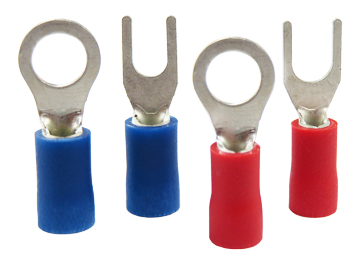
What Is a Semi-Insulated Crimp Terminal?
Crimp terminals connect cables to electrical equipment and help transfer power and signals.
It is widely used in electrical engineering, measuring equipment, FA control equipment, and household appliances.
It was developed around 1925, before crimp terminals became popular and soldering was mainstream.
Advantages of Using Semi-Insulated Crimp Terminals
Cables and electrical equipment can also be connected by soldering or wrapping with electrical tape, but crimp terminals provide a cleaner and more reliable connection.
However, soldering requires technical skill and can cause burn risks.
When secured with insulating tape, there is a risk of short circuits and it is difficult to assemble different cable thicknesses/types/standards beautifully.
Crimp terminals eliminate the need to worry about burns or connections between different cables.
Semi-insulated crimp terminals
Our company offers two types of semi-insulated crimp terminals, R type and Y type, which are sheathed.
-
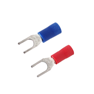
Semi-insulated crimp terminals (Y type/open-end)
-
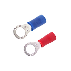
Semi-insulated crimp terminal (round type)
Either crimp terminal type can be selected when it matches the application requirements.
The following section explains the key selection points for choosing the right crimp terminals.
Selection Guide
- 1. "Round type/R type" and "First opening type/Y type"
- The advantage of "round type/R type" is that it is safe.
- The open-end/Y-type design is easy to install and process.
- The choice of whether to focus on safety or workability should be considered based on the actual situation.
| 〇Advantages | ×Disadvantages | |
|---|---|---|
| Round/R type | good security Cheaper than Y-type products Ex. Even if the screws are a little loose, they still stay connected. ※*Looseness enough to lift the terminal may cause sparks. |
Poor processability Ex. The screws must be completely removed and installed. |
| Pre-opening type/Y type | good processability Ex. Can be installed immediately without removing screws. |
Poor security The price is slightly higher than the round type Ex. If the screw is loose, it may fall off directly. Ex. There is a risk of direct contact with electricity. |
- 2. Advantages and Disadvantages of Semi-Insulated Type
- Semi-insulated terminals allow greater flexibility in installation position.
- Because no additional insulation work is required after installation, wiring is faster and easier.
- However, the downside is that the price is slightly higher than "bare" crimp terminals.
- If you have no experience, you may prefer to choose the "semi-insulated" type.
| 〇Advantages | ×Disadvantages | |
|---|---|---|
| Semi-insulated | Installation location is not restricted No insulation required For example: bare, add protective cover. |
Price higher than bare crimp terminals |
The choice of crimp terminals is usually based on the user's preference.
Experienced engineers often make choices based on past experience.
However, if you have no experience and don’t know where to start when choosing a judgment benchmark
If you have any questions or unclear points about crimp terminals, please contact us to answer your questions.
Specifications
| Material | Acid-free copper (body) Polyvinyl chloride (sheath) |
|---|---|
| Rated Voltage | 600V |
| Quantity | 100 |
Y type dimensional drawing
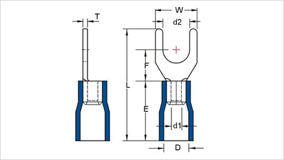
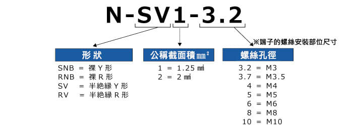
| Model | Nominal Cross-Sectional Area (mm) | Screw Hole Diameter | Dimensions of Each Part (mm) | Applicable Cable Standards | ||||||||
|---|---|---|---|---|---|---|---|---|---|---|---|---|
| ød2 | W | F | L | E | øD | ød1 | T | Stranded Cable mm² | AWG | |||
| N-SV1-3.2 | 1.25 | M3 | 3.2 | 5.7 | 6.5 | 21 | 10 | 4.0 | 1.7 | 0.75 | 0.5-1.5 | 22-16 |
| N-SVS1-3.7 | M3.5 | 3.7 | 5.7 | |||||||||
| N-SVS1-4 | M4 | 4.3 | 6.4 | |||||||||
| N-SVM1-4 | 4.3 | 7.2 | ||||||||||
| N-SV2-3.2 | 2 | M3 | 3.2 | 5.7 | 4.5 | 2.3 | 0.80 | 1.5-2.5 | 16-14 | |||
| N-SVL2-3.7 | M3.5 | 3.7 | 6.0 | |||||||||
| N-SVM2-4 | M4 | 4.3 | 7.2 | |||||||||
Type R Dimensions
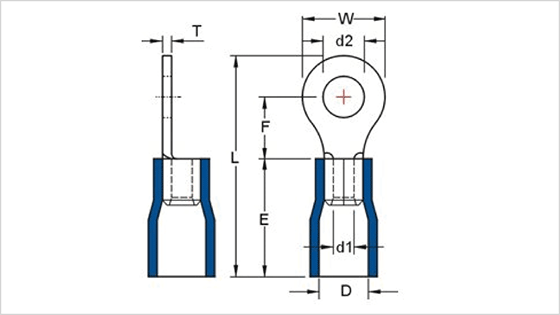
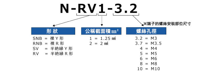
| Model | Nominal Cross-Sectional Area (mm) | Screw Hole Diameter | Dimensions of Each Part (mm) | Applicable Cable Standards | ||||||||
|---|---|---|---|---|---|---|---|---|---|---|---|---|
| ød2 | W | F | L | E | øD | ød1 | T | Stranded Cable mm² | AWG | |||
| N-RV1-3.2 | 1.25 | M3 | 3.2 | 5.5 | 5.0 | 17.5 | 10 | 4.0 | 1.7 | 0.75 | 0.5-1.5 | 22-16 |
| N-RVM1-3.7 | M3.5 | 3.7 | 6.6 | 6.3 | 19.4 | |||||||
| N-RVS1-4 | M4 | 4.3 | 6.6 | 6.3 | 19.4 | |||||||
| N-RVL1-4 | 4.3 | 8.0 | 7.0 | 20.8 | ||||||||
| N-RV1-5 | M5 | 5.3 | 8.0 | 7.0 | 20.8 | |||||||
| N-RVS2-4 | 2 | M4 | 4.3 | 6.6 | 6.3 | 19.4 | 4.5 | 2.3 | 0.80 | 1.5-2.5 | 16-14 | |
| 4.3 | 8.5 | 7.8 | 21.8 | |||||||||
| N-RVS2-5 | M5 | 5.3 | 8.5 | 7.8 | 21.8 | |||||||